|
|
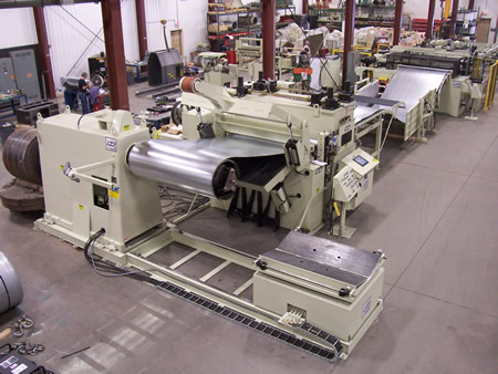
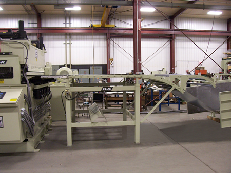
Come and explore how the B&K® Precision Leveler
can improve your metal forming, cut-to-length or job shop business.
To speak directly to a trained application engineer please give us a call today
800 247-2645 x205
Or to reach a trained member of the Formtek-Maine Service Team,
800 247-2645
x302 |
|
|
|

System Specifications:
Material Yield Strength:....................................................30,000-55,000 psi
Material Finish:................................................................critical
Feeder Roll Position Accuracy:..........................................± .002 in.
Max. Line Speed:............................................................150 fpm
Max.
Shear Speed:.................................................................40 spm
Max.Part Length:.............................................................168 in.
Min. Part Length:.............................................................18 in.
Max. Material Width:........................................................72 in.
Min. Material Width:.........................................................6 in.
Max. Material Thickness:..................................................0.135 in.
Min. Material Thickness:...................................................0.021 in.
Max. Stack Weight:..........................................................10,000 lb.
Max. Stack Height:..........................................................24 in.
Max. Coil Weight:............................................................40,000 lb.
Max. Coil O.D.:...............................................................72 in.
Min. Coil O.D.:................................................................28 in.
Max. Coil I.D.:................................................................24 in.
Min. Coil I.D.:.................................................................20 in.
Power requirement
One drop at the servo Feed location..................................460/3/60 200 Amps
One drop at the leveler drive location................................460/3/60 300 Amps
Line direction..................................................................TBD
Length Tolerance, up to 0.135 thick: single sheet
up to 72 part length ± 0.005 in
MODEL 40060-CLC COIL LOADING CAR
FEATURES:
- Rugged steel weldment chassis.
- Flanged steel wheels for guided traverse on track.
- All four wheels are power driven for extra traction to accommodate uneven load or adverse track conditions.
- Rugged physical stops are located at track ends.
- Lift limits have hydraulic overload protection.
- Power cords are protected within heavy duty steel links which extend and retract with traverse.
- The "Vee base" lifting platform is skirted to enclose drive and lift mechanisms.
- Track, integrally mounted with the CWP uncoiler cabinet, has provisions for lagging to the floor, and length for sufficient traverse to clear the mandrel with the widest coil.
- Anti tip arms to stabilize narrow width coils are permanently attached to ensure availability and are readily swung in or out to encourage their employment.
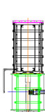
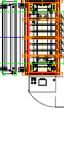
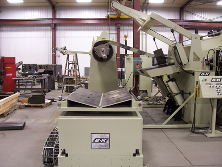
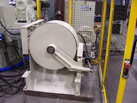
MODEL 9R-72 9R SERIES UNCOILER
FEATURES:
- Unit is mounted on a rugged, steel weldment, cabinet style base.
- Cabinet has provisions for its recommended lagging to the floor.
- An ultrasonic variable tension two-pressure air drag brake monitors the coil O.D. and regulates brake as coil O.D. is reduced.
- The three-arm full radius drum mandrel design provides durable support and superior loading access.
- The hydraulic expansion mechanism uses a sturdy sliding wedge arrangement for ample range and uniform leverage throughout.
- Self-centering expansion arms have broad surfaces and are ruggedly fabricated with tungsten steel inserts for strength and parallelism.
- Black oxided expansion arms protect stock and tooling from paint contamination while resisting corrosion.
- The high tensile, steel alloy spindle is mounted in double row, spherical roller bearings located directly in each face of the cabinet for support close to the load and at optimum spacing.
- Lubrication fittings are made readily visible and accessible.
- Unit is equipped with data plates and cautionary signs, and comes with a comprehensive operation and maintenance manual to foster safe, trouble-free performance.
- Positioning scale is located in one mandrel to assist in proper positioning of the coil during the loading process.
- Hydraulically adjusted sub-base allows 6 inches (+/- 3) of travel of the uncoiler to facilitate coil alignment with mating equipment. Sensors monitor the edge of the coil and adjust reel accordingly.
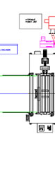
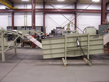
MODEL 72HDP HOLD-DOWN-PEELER SYSTEM
FEATURES:
- A hold-down arm, mounted to the self standing base and extending to the centerline of the coil, is raised and lowered by two large bore air cylinders and has a polyurethane covered rider roll for stock protection and extra threading traction.
- A rugged motor drive to the rider roll helps direct the outer wrap of material toward the leveler when the reel is inched, and a torque limiter arrangement prevents overdriving the stock while maintaining a tight coil.
- A breaker bar, affixed to the hold-down arm, can be used with the tip of the peeler table to backbend the lead edge of the coil in preparation for threading.
- A pneumatically raised and lowered peeler table, mounted to the entry end of the leveler, helps guide material from the reel at the appropriate angle for various coil diameters.
- An air extendible peeler blade, mounted within the peeler table, can be positioned directly under the lead edge of coils that are as small as 16 under full O.D. capacity, thereby fully guiding material during the threading process.
- Handwheel adjusted, self-centering, entry edge guides permit easy stock width adjustments from the operator side of the machine.
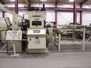
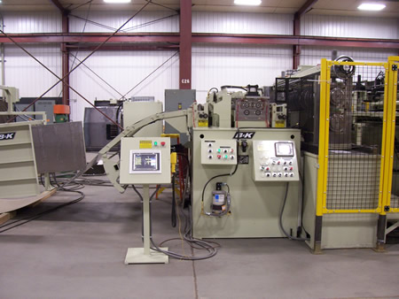
- Consolidated System Control Package includes solenoid operated valving with pushbutton controls and our exclusive Auto Ready function, which moves all threading features to a neutral position in preparation for automatic operation.
- A full diagnostic touchscreen operator interface utilizes a multi-color display and input panel. The interface provides complete operator prompting of threading procedures, a maintenance schedule with service points for the entire system, on-screen digital roll position readouts, and in-depth diagnostic fault messages with recommended remedies.
- System integration package includes wiring harnesses between machines encased in flexible conduit. Wiring includes E-stop, Tight Loop, straightener and/or uncoiler run tie-ins, and any other options or features that require integration.
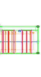
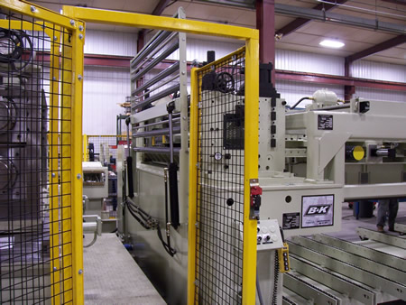
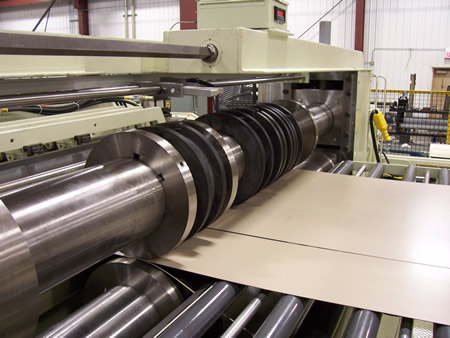
MODEL B&K 84 /1.750/19/9/7/5- HI B&K PRECISION LEVELER
FEATURES:
- Leveler is housed in an upper and lower frame weldment. constructed from heavy structural plate to form a rigid support.
- No special foundations are required due to the heavy duty structural sections.
- Leveler rolls are manufactured from 52100 material, cryogenically processed and heat treated to 62-64 Rockwell C scale.
- Leveler rolls are supported for both radial and thrust loading through large journal bearings.
- Leveler rollers are backed up by high quality cam follower bearings.
- Cam follower bearings are specially made with a hardened crowned surface to reduce roller marking.
- Power is efficiently distributed to all leveling rolls by a transmission gearbox driving high quality universal joints.
- Transmission gearbox is made of fabricated steel sections, having machined surfaces carefully, machined and bolted together to form an oil tight gearcase.
- Dual herringbone gear drive system allows smooth performance and eliminates chatter and end thrust for longer service life.
- A gear driven circulating oil system lubricates the gears only when machine is in operation.
- An automatic central lubrication system with pump and timer facilitates maintenance.
- Top bank of leveler rolls has a simple, two point motorized tilt adjustment.
- Two high capacity jackscrews coupled together at the leveler entrance and two at the exit provide the leveler head tilt.
- Powered high rise head feature allows leveler to open for easy access to the work rolls for cleaning and inspection.
- Leveler base has a machined groove around the lower roll flight, plumbed to a pipe drain, to allow any oil which is removed from the material to flow to a customer supplied oil tank.
- Upper backup sections are mounted in fixed positions.
- Lower backup sections mounted next to the leveler roller journal are mounted in fixed positions while center backup sections are powered by motorized jackscrews.
- An ultrasonic sensor monitors material position in the loop and adjusts leveler speed accordingly, through a microprocessor control.
- A modulating drive system automatically regulates the output speed of the machine to the demand of slack material, providing smooth delivery without sudden starts and stops.
- Large heavy duty powered pinch rolls to enable pull-off operation from a large capacity non-powered uncoiler. Also allows leveler to thread-up without disrupting work roll settings.
- Controls, including forward and reverse jog, leveler head tilt and backup roll adjustments, are positioned for operating convenience and adjustment accessibility.
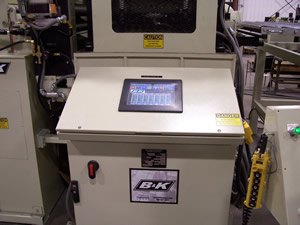
- Digital position readouts for leveler head tilt and backup roller positions are provided on a touchscreen panel.
- Pictoral touchscreen control provides ease of set up and operation, even for operators with marginal training. Automatically recalls job settings to improve productivity. Complete with on screen diagnostics, machine specifications and maintenance screens.
- Full width intermediate rolls for added protection when processing critical finish materials.
- The drive and power train are totally enclosed and the unit comes with data plates, cautionary signs and a comprehensive operation and maintenance manual to foster safe, trouble-free performance.
MODEL 72IC INSPECTION CASCADE
FEATURES:
- Rugged steel weldment base structure.
- PVC full width rolls to allow support of the material for visual inspection to ensure material defect have been removed before threading the entire system.
- Entry section of cascade has a flip open design with counter weight to allow easy access to clean the leveler work rolls.
- Adjustable radius section of inspection table allows for the proper alignment of material into the looping area.
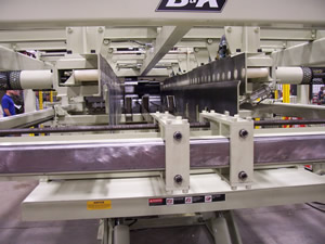
MODEL 72PTT21 PNEUMATIC THREADING TABLE
FEATURES:
- The threading table is formed of two steel frames in a ruggedly fabricated construction.
- Each surface is topped by solid sheet steel to avoid the stock hangups of rail construction.
- Gull wing lift is provided by air cylinders with solenoid operated valving and controls conveniently positioned at the operator station of the straightener.
- When elevated, the tables form a surface to span the looping area for threading between straightener and feed.
- When in the lowered position the tables form a barrier to both sides of the looping area.
MODEL SMXHD72SE4 FOUR ROLL, HEAVY DUTY SERVOMAX ELECTRIC ROLL FEED
Servo driven 4-roll feeds are state-of-the-art devices meeting modern production demand for delivering coil stock material to CTL/blanking operations with unprecedented speed and accuracy. The four roll feed allow for twice the surface contact area with half of the rolls pressure of conventional two roll feed units. To achieve highest output rates, uncoiler and leveler equipment must sustain both the linear output and response rates necessary to support the feed. Adequate slack material must be furnished and controlled properly. There is no substitute for a fully coordinated CTL/blanking system in meeting these considerations and thus achieving optimum productivity.
FEED FEATURES:
- The unit is powered by a modern, low-inertia, high performance servomotor for efficient response to feed-to-length demands.
- Roll positioning is continuously monitored by a low-inertia resolver.
- The closed loop control system dictates positioning accuracy of plus or minus .002" at any settable length.
- The accel/decel slope is pre-programmed in an optimized trapezoidal velocity profile to minimize stock slippage and deliver accurate lengths in a timely manner without impractical operator interpretations.
- Low inertia feed rolls are constructed of 4" diameter, 5/8" wall high strength tubing.
- Roll width maintains full stock contact and ample clearance at rated capacity.
- A matte chrome finish on the hardened and ground rolls improves wearability and traction.
- The top rolls are opened and closed via solenoid operated valving and two air cylinders for pilot release and powerful clamping without adjustment for stock thickness.
- Anti backup rolls, which prevent the pullback of stock during feed roll release, are pneumatically opened for threading.
- A heavy duty, precision gear reduction operates in a bath of oil to efficiently transfer power to the feed rolls with continuing accuracy.
- Five, zero backlash, universal couplings transfer power from the motor to the gearbox and on to all four feed rolls in the most efficient and serviceable, in line drive style.
- Entry and exit handwheel adjusted self centering edge guides with slip gear arrangement for off center when required allows adjustability from operator side of the feed.
- An automatic central lubrication system with air pump and electric timer facilitates maintenance by ensuring properly metered lubrication to critical points.
- Massive, 3" thick upright roller housings employ dual bearing arrangements for each end of each roll.
- The four roll design permits unparalleled tractions on the stock without the geometric increase in roll inertia that large diameter rolls would cause.
- Low inertia, moderate diameter rolls are enabled for high capacity stock feeding by an exclusive roll backup arrangement which prevents deflection, maintains parallelism.
- A rugged steel weldment cabinet is furnished to a fixed passline height suited to the application.
- Entry cascade rolls support the material in a gradual arc coming out of the looping area.
- Touch screen operator control with 500 job memory, jog to length, in motion part length compensation and ten different speed selections.
MODEL 72HOS HYDRAULIC OPERATED SHEAR
FEATURES:
- Rugged steel weldment construction with built-in rigidity to shear very narrow strips of full capacity material, without off-setting.
- Box-type bed contains the lower blade and is easily adjusted for blade clearance takeup.
- Bronze wearite gib bearings are located on front, back and ends of the crosshead.
- Tapered gib spacers permits setting close clearance in the gib ways for superior blade alignment resulting in quality sheared edges.
- Blades are manufactured with high carbon, high chrome steel of uniform hardness and grain structure.
- Top Blade is reversible with 4 cutting edges.
- Bottom blade is reversible with 4 cutting edges.
- Single point blade gap adjustment via handwheel control. Dial indicators are provided for quick visual reference to blade gap adjustment.
MODEL SLT7210 SLITTER
FEATURES:
- Slitting is accomplished on a common pair if arbors and high-carbon, high chrome knives.
- Five sets are included as standard which allow processing of 4 blanks with edge trim. (Additional knives are available as an option.)
- One set of rubber stripper rings are provided with every set of slitter knives.
- The lower slitter arbor is driven for positive speed control.
- All knives are easily adjustable horizontally, and the top arbor is adjustable vertically, as well.
- Slitter knives have the capacity of slitting on either side.
- The knives can be quickly moved on the arbor to the proper location using a digital slitter knife position indicator.
- Once the knives are in location they are quickly locked by the use of an Allen wrench on two setscrews.
- A swing away arbor on the slitter assembly permits a faster slitter knife service. This feature helps insure greater productivity.
Scrap Winder
FEATURES:
- Heavy welded plate steel frame
- Bundle fully guarded during winding.
- Tapered center cone supports bundle during winding.
- Driven rotating side plates confine scrap during winding.
- Rotating side plates supported in anti-friction bearings.
- Winder is driven by hydraulic motor through chain and sprocket transmission.
- Center cone supported in anti-friction bearings.
- Center cone slotted for entering scrap lead ends.
- Level wind eye assures uniform bundle buildup.
- Level wind driven at winder speed.
- Level wind equipped with replaceable hardened ring.
- Scrap tension adjustable from operators console through flow control valves.
- Outboard support plate is powered with a hydraulic cylinder to open and close.
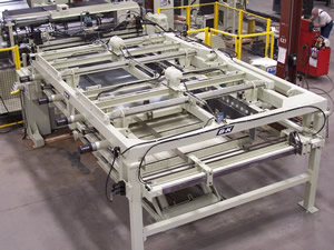
MODEL 72-168 PSPT PART STACKER AND PALLET TRANSFER SYSTEM STACKING STATION
FEATURES:
- Automatically lowering hydraulic lift platform with powered conveyor to discharge full pallet. The platform lowers to align with discharge conveyor and is movable to allow centering of stack on pallet.
- Stacking station has adjustable side guides and end stop. Side guides are power adjusted with digital readout and the end stops are manually adjusted and are provided with scale and pointer for positioning.
- Stacker is equipped with three dividers to separate the individual blanks being cut. The dividers are power inserted with digital readout for quick positioning. The number of dividers used would depend on number of parts required.
- Four end stops are included to help align up to four blanked sheets. These would be hand cranked into position as required.
- Side load chain conveyor for empty pallet insertion.
- Side chain discharge conveyor for full pallet removal.
Note: All CTL systems are set up at our B&K facility and tested under power. This allows us to inspect all operations of the system prior to shipment. We recommend that sample material be provided for a trial run off as well.
|
|
 Precision Levelers for the 21st Century